ComfyUI is a powerful visual programming tool for creating AI workflows, particularly for image generation. One of its standout features is the color-coded connection wires, which indicate the strict data types used in the system. This guide will help you understand how parameters and data types work in ComfyUI, along with practical tips for optimizing your workflows.
Table of Contents
Color-Coded Connection Wires: What They Mean
In ComfyUI, the color coding of connection wires reflects the strict data type system. Each wire color represents a specific type of data being transmitted between nodes. This ensures compatibility and prevents errors when connecting nodes.
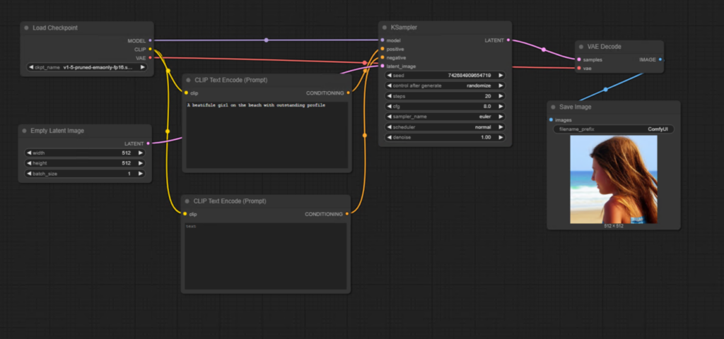
Common Wire Colors and Their Meanings:
- Lavender: Represents the Diffusion Model connection.
- Rose: Indicates the VAE Model connection.
- Yellow: Used for CLIP Model connections.
- Orange: Represents Conditioning Wires, which are outputs of CLIP prompt nodes.
- Pink: Transmits Latent Images.
- Muted Gray-Green: Represents Integer Values, such as width and height parameters.
These color codes help users immediately identify what can and cannot be connected. For example, a Diffusion Model wire cannot be connected to a VAE input, as they are incompatible.
Working with Parameters in Nodes
Each node in ComfyUI has parameters that define its behavior and functionality. These parameters can be adjusted using widgets or converted into inputs for dynamic control.
Types of Parameter Widgets:
- Data Entry Fields: For example, the width and height parameters in the Empty Latent Image Node allow users to manually input values like
512or1024. - Dropdown Menus: Some parameters, such as the “Control After Generate” option in the K Sampler Node, allow users to choose between options like:
- Fixed
- Randomized
- Increment or decrement the seed number after each generation.
Converting Widgets to Inputs
Sometimes, you may want to dynamically control a parameter by connecting it to another node. To do this, you can convert a widget to an input. Here’s how:
Steps to Convert a Widget to an Input:
- Right-Click on the Node: Open the context-sensitive popup menu.
- Choose “Convert Widget to Input”: Select the parameter you want to convert, such as width or height.
- Connect a Node to the Input: For example, use a Primitive Node to set values dynamically.
Once converted, the widget disappears, and a slot or port appears for connecting other nodes. This method is especially useful for automating workflows, such as always generating square images by linking width and height parameters.
Using the Primitive Node for Dynamic Values
The Primitive Node is a versatile tool for setting dynamic values for parameters. It can store and transmit integer values, such as the width and height of an image, while offering additional controls.
Features of the Primitive Node:
- Value Persistence: By default, the value remains fixed after each generation.
- Dynamic Options: You can increment, decrement, or randomize the value after each generation.
To create a Primitive Node:
- Drag out from a slot or port.
- Select Add Node from the popup menu.
- Choose Primitive under the Utils category.
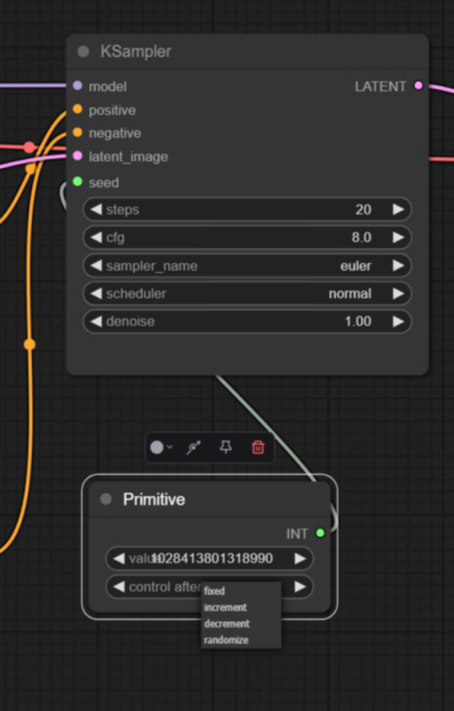
The above setting is controlling increase or decrease/fixed the seed value after each image generation.
Resolution and Model Compatibility
Choosing the right resolution for your workflow is crucial, as it directly affects the quality of the generated images. For example:
- Stable Diffusion 1.5 was trained on images with a resolution of 512×512 pixels. Using this resolution ensures optimal results.
- Higher Resolutions (e.g., 1024×1024): May result in distorted images because they exceed the model’s training dataset.
- Lower Resolutions (e.g., 256×256): Often produce abstract or unusable results.
Example Workflow:
- Set the resolution of the Empty Latent Image Node to
512x512. - Generate an image using a fixed seed.
- Observe how changing the resolution affects the output:
- 512×512: Produces a clear and accurate image.
- 1024×1024: Results in bizarre structures due to incompatibility with the model’s training dataset.
- 256×256: Produces distorted abstractions.
Tips for Optimizing Resolution and Aspect Ratios
If you need to use different aspect ratios while retaining compatibility with the model, you can adjust the resolution while keeping the overall pixel count consistent. This ensures better results without compromising image quality.
Key Takeaways
- Color-coded wires indicate strict data types in ComfyUI, ensuring compatibility between nodes.
- Parameters can be adjusted manually or dynamically by converting widgets to inputs.
- The Primitive Node allows for greater flexibility in setting and controlling values.
- Choosing the correct resolution for your model is essential for generating high-quality images.
By understanding these concepts, you’ll be able to design efficient and error-free workflows in ComfyUI, unlocking its full potential for AI image generation.